Flexible PCBs
Flexible PCB with Stiffeners
A flexible circuit example with locally supported connection areas. Share the fit, bend and connector drawings.
- Material direction
- Flexible circuit material — project-defined
- Project focus
- Bend zones & connection geometry
- Manufacturing basis
- Current drawings & engineering review
Product overview
Designed into
your next product.
Start with how the circuit fits, bends and connects within your product. Distinguish installation bends from movement during operation.
Connections shaped around the product.
Review the flexible circuit outline, conductor layout and connection zones alongside the enclosure. Identify support areas and describe the intended movement before defining the construction.
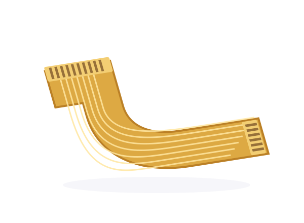
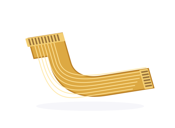
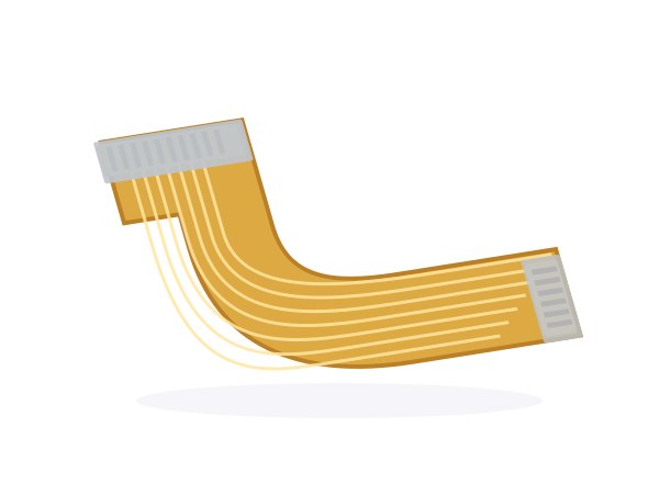
Product type illustration. Materials, construction and final specifications are confirmed for your project.
Application considerations
- Compact electronic connections
- Shaped installation paths
- Connector and moving-interface design
Product specifications
Define the details.
Set the manufacturing brief.
Start with the information already defined in your design. Bring open requirements to the engineering review.
- Product
- Flexible PCB with Stiffeners
- Product family
- Flexible PCBs
- Material direction
- Flexible circuit material — project-defined
- Construction
- Local support · Connector areas
- Board geometry
- Outline, dimensions and mounting — per current drawing
- Copper & surface finish
- Requirements to be confirmed in the fabrication brief
- Bend & installation requirements
- Bend zones, intended movement, support and connector geometry
- Inspection & acceptance
- Inspection method and acceptance criteria agreed per project
Engineering review
Connect the board
to the build.
Review the flexible circuit outline, conductor layout and connection zones alongside the enclosure. Identify support areas and describe the intended movement before defining the construction.

Stiffener placement and outline
Connect the current revision and requirements to this review point. Confirm the agreed manufacturing input before proceeding.
Connector fit and installation
Connect the current revision and requirements to this review point. Confirm the agreed manufacturing input before proceeding.
Bend zones and assembly drawings
Connect the current revision and requirements to this review point. Confirm the agreed manufacturing input before proceeding.
Project files
Bring your design.
We’ll discuss the next step.
Circuit data, outline drawing, bend requirements and stiffener details.
Prepare a Product Enquiry- 01
Current design files
Gerber files, drill data and fabrication drawing with the current revision.
- 02
Materials & interfaces
Bend zones, intended movement, support and connector geometry
- 03
Assembly information
BOM, placement data and assembly drawings when assembly is part of your enquiry.
- 04
Quantity & acceptance
Project stage, quantity, target timing and inspection or test requirements.